
GD&T Basics - a comprehensive summary of Geometric dimensioning and Tolerancing (gd&t)
a list of all the gd&t symbols, the basics of gd&t explainted, download the printable cheat sheet (wall chart), watch the summafry video, and more..
have the important information always ready at your fingertips

The basics of gd&t and list of symbols.
GD&T (Geometric Dimensioning and Tolerancing) is a system of tolerating parts and assemblies on engineering technical drawings to communicate geometric requirements. GD&T is widely used in the manufacturing industry to ensure that parts and assemblies meet precise specifications. In the following sections we will look into in more detail.
|
 |
|
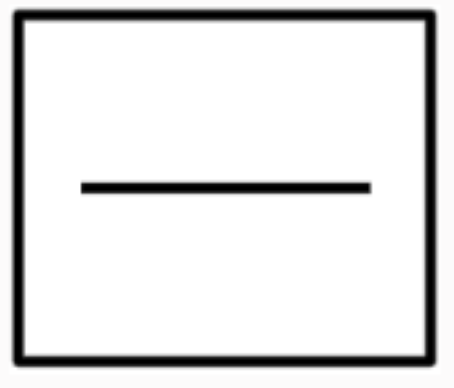
The line that is pointed at by the arrow (leader) should lie between two Ideal lines that are parallel to each other, and the distance between these two planes is the value of the tolerance. Example of a drawing entry: 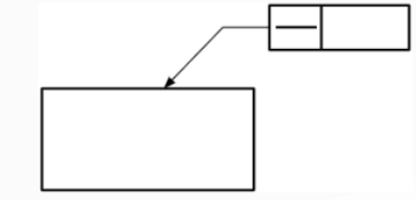 The tolerancezone of this example would look like this: The tolerancezone of this example would look like this: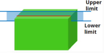 red: the tolerated element blue: the limits of the tolerance zone | |
|
 |
|
The surface that is pointed at by the arrow (leader) should lie between two Ideal planes that are parallel to each other, and the distance between these two planes is the value of the tolerance. Example of a drawing entry: 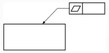 The tolerancezone of this example would look like this: The tolerancezone of this example would look like this: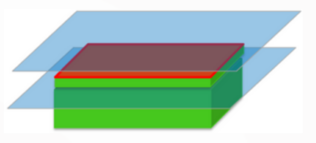 red: the tolerated element blue: the limits of the tolerance zone | |
|
 |
|
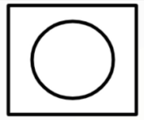
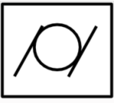
The circle that is pointed at by the arrow (leader) should lie between two Ideal circles that are concentric with each other, and the distance between these two circles is the value of the tolerance. Example of a drawing entry: 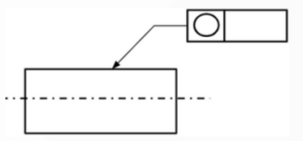 The tolerancezone of this example would look like this: The tolerancezone of this example would look like this: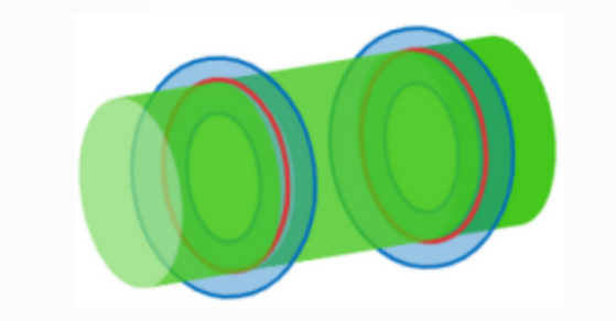 red: the tolerated element blue: the limits of the tolerance zone | |
|
 |
|
The cylinder that is pointed at by the arrow (leader) should lie between two Ideal cylinders that are concentric with each other, and the distance between these two cylinders is the value of the tolerance. Example of a drawing entry: 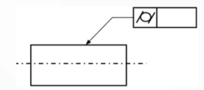 The tolerancezone of this example would look like this: The tolerancezone of this example would look like this: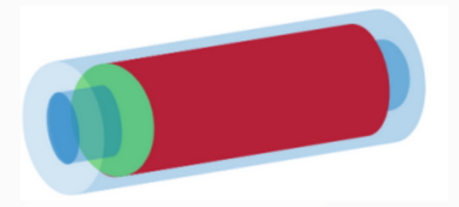 red: the tolerated element blue: the limits of the tolerance zone | |
|
 |
|
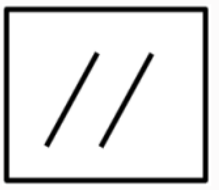
The feature (line, centerline or planar surface) that is pointed at by the arrow (leader) should lie between two Ideal planes that are parallel to each other, and are ideally parallel to the datum and the distance between these two planes is the value of the tolerance. If there is a diameter sign added before the value of the tolerance, then the tolerance zone in this case is a cylinder, having a diameter equal to the tolerance value. the centerline of this cylinder is ideally parallel to the datum. Example of a drawing entry: 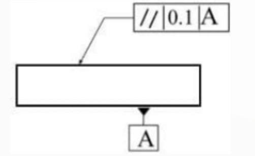 The tolerance zone of this example would look like this: The tolerance zone of this example would look like this: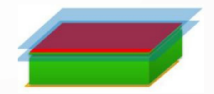 red: the tolerated element blue: the limits of the tolerance zone yellow: the datum (the reference) | |
|
 |
|
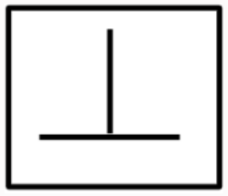
The feature (line, centerline or planar surface) that is pointed at by the arrow (leader) should lie between two Ideal planes that are parallel to each other, and are ideally perpendicular to the datum and the distance between these two planes is the value of the tolerance. If there is a diameter sign added before the value of the tolerance, then the tolerance zone in this case is a cylinder, having a diameter equal to the tolerance value. the centerline of this cylinder is ideally perpendicular to the datum. Example of a drawing entry: 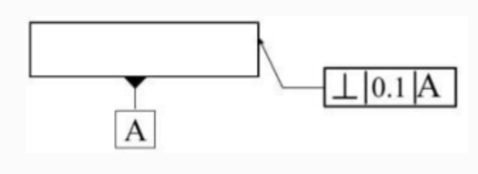 The tolerancezone of this example would look like this: The tolerancezone of this example would look like this: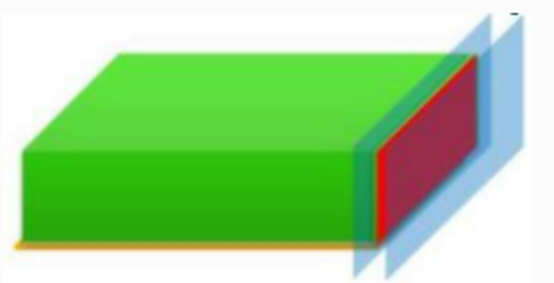 red: the tolerated element blue: the limits of the tolerance zone yellow: the datum (the reference) | |
|
 |
|
The feature (line, centerline or planar surface) that is pointed at by the arrow (leader) should lie between two Ideal planes that are parallel to each other, and have a theoritically exact angle to the datum and the distance between these two planes is the value of the tolerance. If there is a diameter sign added before the value of the tolerance, then the tolerance zone in this case is a cylinder, having a diameter equal to the tolerance value. the centerline of this cylinder has a theoreticaly exact angle to the datum. Example of a drawing entry: 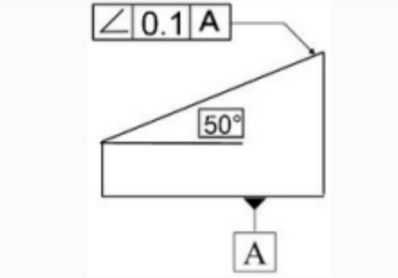 The tolerancezone of this example would look like this: The tolerancezone of this example would look like this: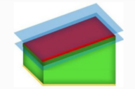 red: the tolerated element blue: the limits of the tolerance zone yellow: the datum (the reference) | |
|
 |
|
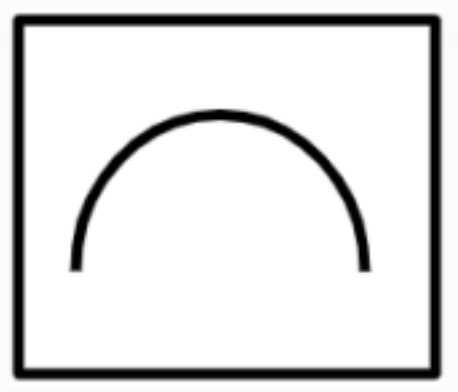
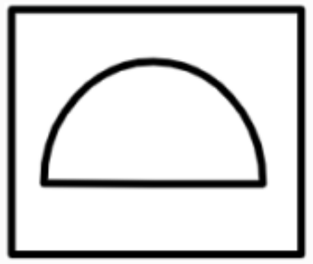
Any line on the profile that is pointed at by the arrow (leader) should lie between two Ideal linear profiles that are offset from each other, and the distance between these two profiles is the value of the tolerance. Example of a drawing entry: 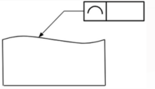 The tolerancezone of this example would look like this: The tolerancezone of this example would look like this: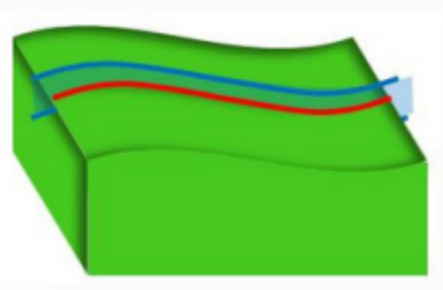 red: the tolerated element blue: the limits of the tolerance zone | |
|
 |
|
The profile that is pointed at by the arrow (leader) should lie between two Ideal profiles that are offset from each other, and the distance between these two profiles is the value of the tolerance. Example of a drawing entry: 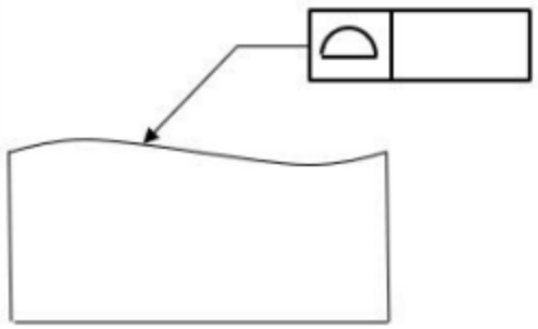 The tolerancezone of this example would look like this: The tolerancezone of this example would look like this: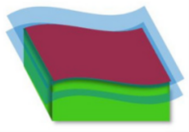 red: the tolerated element blue: the limits of the tolerance zone | |
|
 |
|
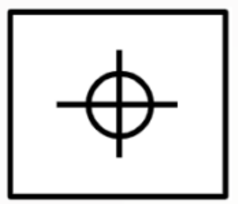
Position specifies that the tolerated feature should lie in a tolerance zone which has a certain location in the part with respect to other features. Position needs a datum and theoretical dimensions. So this specification means that the tolerated centerline of the hole should lie inside a tolerance zone which is a circle with diameter of 0.1. The position of the centerline of this circle lies in a distance of 10 to datum A and 10 to datum B Example of a drawing entry: 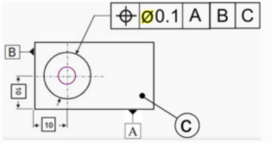 The tolerancezone of this example would look like this: The tolerancezone of this example would look like this: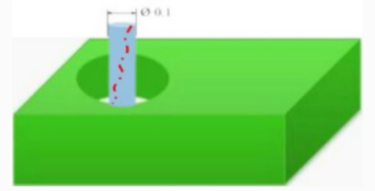
| |
|
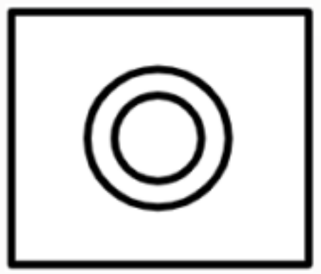 |
Concentricity or coaxiality indicates that the centerline of the tolerated circle lies in a tolerance zone which is a circle with a diameter of the tolerance value. This circle has the same centerline as the datum. 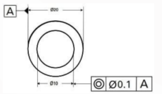 Example of a drawing entry: Example of a drawing entry:The tolerancezone of this example would look like this: 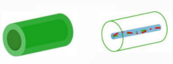
| |
|
 |
|
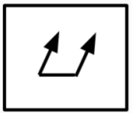
The part should be rotated around datum A, a measurement gauge is pressed to the surface of the tolerated cylinder and the gauge reading is set to zero. By rotating the part, the gauge indicates if there is a difference in height between the different points on the rotated circumference. This difference in height is the value of the run out. Example of a drawing entry: 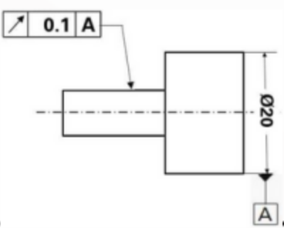 The tolerancezone of this example would look like this: The tolerancezone of this example would look like this: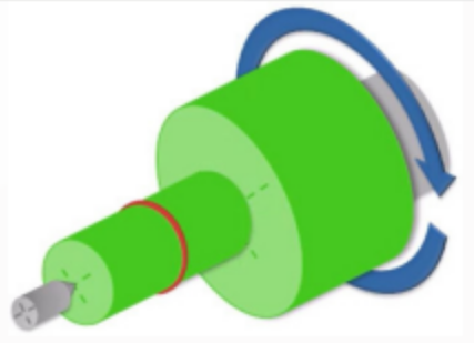
| |
|
 |
| The measurement method of the total runout is similar to this of the circular run out, but here, the evaluation is done on the complete cylinder and not on only one section of it. Example of a drawing entry: 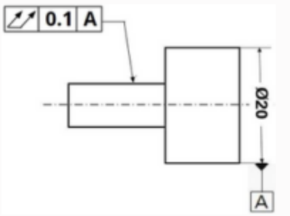 The tolerancezone of this example would look like this: The tolerancezone of this example would look like this: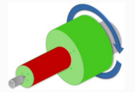 | |
|
|
| here, the tolerated feature is not a cylinder, but a planar surface.The evaluation is carried out on each circle on the surface independently. Example of a drawing entry: 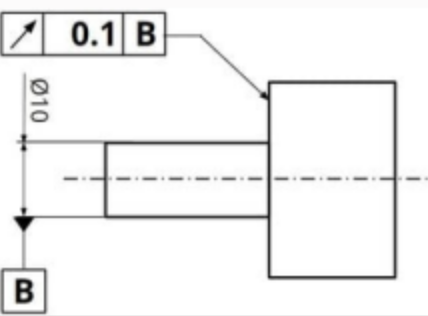 The tolerancezone of this example would look like this: The tolerancezone of this example would look like this: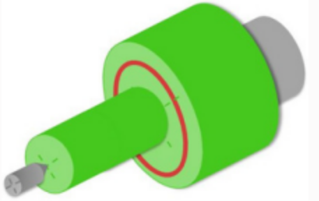 | |
|
|
|
here, the tolerated feature is not a cylinder, but a planar surface. The evaluation is carried out on the complete tolerated feature. Example of a drawing entry: 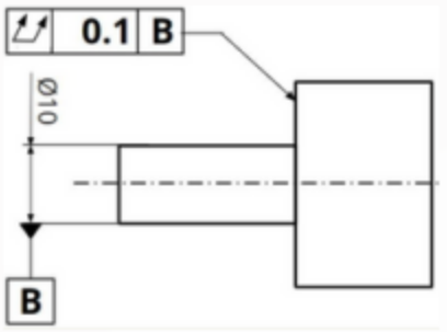 The tolerance zone of this example would look like this: The tolerance zone of this example would look like this: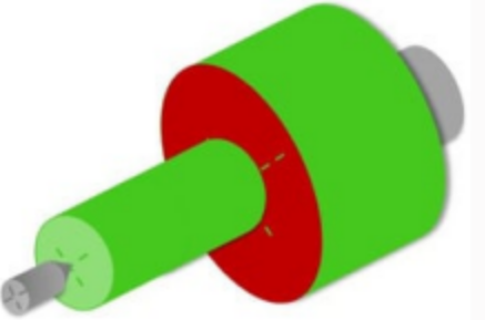
| |
.png)
Elevate your engineering skills with our comprehensive GD&T Training course. This training covers both ISO GPS and ASME Y14.5 standards, ensuring you master the essential principles of GD&T.
$250
.png)
The Engineering Drawing course covers the basics of creating technical drawings used in various engineering disciplines. Students learn about the principles of orthographic projection, dimensioning, and tolerancing.
$160